
The number one issue which results in poor edgeband quality is chipped edges at the banding/panel interface.
A major cause of rejected panels is chipped edges on the surface of TFL (thermally fused laminate/melamine) or HPL panels. This is normally caused by a dull router bit if panels are nested on a CNC router, dull or warped saw blade on a saw, scoring blade not aligned with main blade, or an out of square pressure roller/glue roller. Chipping on the top and bottom of the panel cut on a saw is normally from a bad main blade. Chipping on the bottom only of a panel cut on a saw is usually due to a bad, misaligned or missing scoring blade. Nesting routers can sometimes fracture the edge but not actually loosen the chip. Once this panel is edgebanded, the pressure rollers that close the top/bottom of the banded edge will pop the chip loose.
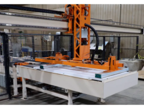
Many companies are making the decision to purchase an edgebander with pre-mill since this can all but eliminate chipped edges due to panel sizing or nesting. It can also remove a score line that was set too deep for whatever reason. Pre-milling can remove up to 3mm of wood which can usually get even the largest chips. Of course, the user must compensate for the change in panel dimension.
If your edgebander has pre-mill and it is being used and you still have chipping, first closely inspect the pre-mill cutters for glue and resin buildup as well as chipping or excessive wear. If you are not using diamond tooling in the pre-mill you should invest in it. Carbide cutters can wear out in a short time, especially at the laminate edge. Diamond cutters on the other hand, can last in excess of one year. Even with sharp tools, glue and resin build up can cause chipping on TFL, especially if it is brittle or thin.
Another possible cause for chipping is misalignment of the panel edge and the application roller. If the angle is severe enough, the glue roller contacting only the upper or lower edge can cause chipping. Use a precision square and verify the panel edge is perpendicular to the face. If not, adjust your panel saw or router for verticality.
The easiest way to check verticality of the glue application roller is as follows:
• Build up a panel to near the maximum thickness accepted by the edgebander
• Trim the edge and verify it is perfectly perpendicular or use the pre-mill if equipped
• Run the panel through the machine with only glue applied to the edge; NO BANDING
• There should be an even spread of glue from bottom to top of the panel.
If necessary, adjust the perpendicularity of the glue roller according to the manufacturer’s specifications until an even coat is applied along the entire length of the panel. If this needs to be adjusted very much, you may need to adjust the rest position and float of the glue pot. Be sure the glue pot moves back 1mm while in contact with the panel.
One additional thing I have run into that causes chipping is related to nested-based CNC cutting. If the tool does not penetrate far enough through the material or the corner of the tool rounds off, a flashing (0.001-0.002 inch) will be left on the bottom edge of the panel that is not visible to the naked eye, but will cause chipping when it comes in contact with the glue roller.
Source: Jason Varelli is the Biesse Brand sales manager, Biesse America. For information call 704-357-3131 or visit Biesse.com.


Have something to say? Share your thoughts with us in the comments below.